

Why Choose Solder Cup Pogo Pin for Manual Soldering?
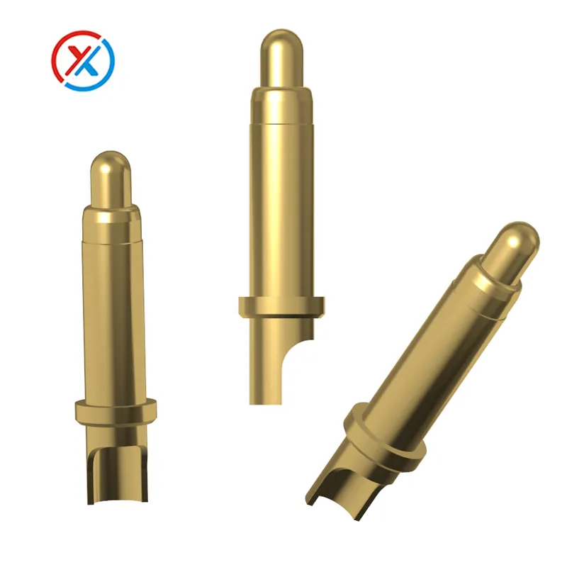
Solder cup pogo pins provide a defined connection point for attaching a wire directly to a spring-loaded contact. The cup sits at the rear of the component, while the plunger at the opposite end remains free to compress against its mating pad.
This arrangement is useful in charging cables, test fixtures, removable modules, and connector assemblies that use wire terminations. For manual assembly, the cup helps locate the stripped conductor and provides an accessible area for forming the solder joint.
Its advantage is practical handling. Joint reliability still depends on wire fit, surface condition, heat input, solder quantity, and mechanical support.
For custom cable and docking projects, we can develop solder cup pogo pin assemblies from customer drawings, coordinating the cup dimensions, contact geometry, insulating carrier, and cable routing. Magnetic housings and device-side mating components can be included where the product requires a complete detachable interface.
Before selecting the contact, review the termination as part of the finished assembly.
| Design item | What to confirm |
|---|---|
| Wire compatibility | Conductor size, strand construction, stripped length, and insertion depth |
| Cup geometry | Internal dimensions, opening direction, and access for the soldering tool |
| Surface finish | Solderability of the termination and compatibility with the selected process |
| Thermal limits | Permitted soldering conditions for the contact, carrier, insulation, and nearby components |
| Mechanical support | Contact retention, cable routing, and strain relief |
| Electrical requirements | Current, allowable voltage drop, insulation spacing, and temperature under load |
Cup dimensions should suit the actual conductor, including any preparation applied before insertion. A stranded wire needs sufficient space for the bundle without loose strands projecting outside the termination.
An oversized cup can make positioning and solder control more difficult. An undersized cup can prevent proper insertion or encourage operators to remove strands. Wire and cup selection should be resolved in the drawing rather than adjusted informally during assembly.
Tool access matters as well. Closely spaced contacts, surrounding plastic, or an awkward cable exit can make an otherwise suitable cup difficult to solder. The assembly sequence may need to allow wire attachment before the contacts are installed in a carrier, provided that sequence is compatible with the design.
The cup helps locate the conductor, but it does not necessarily hold it securely while the solder solidifies. A suitable fixture should support the contact and wire without loading the movable plunger or distorting the barrel.
The finish on the soldering area also needs its own specification. A coating selected for the exposed mating contact may serve a different purpose from the finish on the cup.
Gold can provide a solderable surface when the coating and soldering process are compatible. However, thicker gold is not automatically better for a solder termination. Gold can dissolve into molten solder, and its contribution to the joint metallurgy needs to be considered during process qualification.
The base material, underlayer, surface condition, storage history, solder alloy, and flux all influence wetting. A visibly gold-colored cup is not sufficient evidence that a particular soldering process will produce an acceptable joint.
Solder alloy selection should follow the assembly’s material, operating, manufacturing, and customer requirements. Tin-silver-copper and tin-copper alloys are possible lead-free options, but silver content alone does not establish which solder is best.
Flux should suit the surfaces and alloy, with residue management defined for the finished assembly. Cleaning methods must also be compatible with plating, plastics, adhesives, and wire insulation.
A controlled manual process usually addresses the following steps:
Prepare and inspect the parts. Confirm the contact and wire specifications. Check for damaged plating, contamination, bent features, or poor storage condition. Use an approved cleaning method where necessary; abrasive cleaning can remove a functional finish.
Prepare the conductor. Strip the specified length without damaging strands. Keep the bundle contained and position it to the required insertion depth. Any pre-tinning should be included in the process because it changes the conductor’s dimensions and solder behavior.
Support the assembly. Hold the contact and wire in the required orientation. Keep the mating tip and moving mechanism clear of unnecessary force, solder, and flux.
Apply controlled heat and solder. Heat the termination sufficiently for wetting within the component’s permitted exposure. Control solder quantity and avoid transferring excessive heat into the carrier, insulation, or internal assembly.
Allow the joint to solidify undisturbed. Maintain support until the joint has cooled sufficiently, then complete inspection, insulation, and strain-relief operations.
There is no universal soldering-iron temperature or dwell time for every solder cup pogo pin. Tip geometry, heater capability, cup mass, wire size, solder alloy, and surrounding materials all affect heat transfer.
The displayed iron temperature also differs from the temperature reached at the joint. A process should establish acceptable settings and exposure through representative assemblies rather than relying on a single generic value.
Excessive heating can damage insulation or nearby materials and may affect the contact assembly. Insufficient heat can leave poor wetting even when the solder appears to occupy the cup.
Solder quantity should follow the approved joint geometry. Completely filling every cup to its rim is not a universal acceptance requirement. The joint needs adequate wetting and conductor engagement without overflow, bridging, or interference with adjacent parts.
Visual inspection should check conductor placement, visible wetting, loose strands, insulation damage, and solder reaching unintended areas. A shiny surface is not a universal quality requirement; appearance varies with alloy and solidification conditions.
External inspection also cannot establish that a joint contains no internal voids. Where internal formation is important to qualification, representative samples may require additional examination, such as sectioning.
Mechanical support remains essential after soldering. The cable should not repeatedly bend or pull directly at the joint. Strain relief should distribute loads into the housing or another supporting feature while preserving the intended cable movement.
Electrical continuity confirms that a path exists, but it does not establish current-carrying performance or long-term durability. Evaluation may also include resistance, voltage drop, temperature under load, and insulation between adjacent contacts.
After soldering, check that the plunger compresses smoothly and returns correctly. This helps identify movement problems introduced by heat, contamination, handling, or installation.
For production approval, representative assemblies should also undergo the required cable pull, bending, mating, or environmental tests. These results should remain linked to the wire specification, contact revision, soldering process, and strain-relief arrangement used in the samples.
1. How long does a solder cup pogo pin connection last?
There is no universal service-life figure. Durability depends on joint formation, mechanical support, electrical load, movement, and environment. The solder termination and the spring-loaded mating contact should both be evaluated against the product’s requirements.
2. Which solder alloy is best for solder cup pogo pins?
Use an alloy compatible with the termination finish, wire, thermal limits, and assembly requirements. Neither silver-containing nor silver-free solder is automatically preferable for every design. Confirm the choice through process qualification.
3. Should the solder cup always be completely filled?
No. The required solder quantity depends on the cup and conductor geometry. Follow the approved acceptance criteria for wetting, insertion, fill, and overflow rather than using a universal “fill to the rim” rule.
4. Can solder cup pogo pins be reworked?
They can be reworked when the component and assembly permit it. Control additional heat exposure, inspect the termination and insulation, and verify electrical performance and plunger movement afterward. Replace components that no longer meet the acceptance criteria.
Hot News
-
What products can Pogo pin be used in?
2025-12-02 17:54:19
-
How to solve the overheating problem when charging high-power devices with high-current Pogo Pins?
2026-08-06 14:26:20
-
How to Choose a Magnetic Pogo Pin That Actually Works for Your Product
2026-07-27 13:50:55
-
Advantages of Pogo Pin Charging
2026-07-24 13:56:53
-
Five Core Technologies for Lowering Temperature Rise in High-current Pogo Pin Design
2026-07-18 14:43:29
-
Advantages of POGO Pin Connectors
2026-06-29 14:44:51
-
How Does a Magnetic Data Cable Improve Charging and Data Stability?
2026-03-20 15:06:03
-
How Do Pogo Connectors Compare with Traditional Plug-in Interfaces?
2026-03-20 14:59:33
-
What Makes a Magnetic Pogo Pin Connector Suitable for Custom Docking?
2026-03-20 14:56:27
-
What Is a Pogopin and Why Is It Used in Precision Electronic Connections?
2026-03-20 14:54:13
-
What durability standards matter when sourcing magnetic cables in bulk?
2026-03-20 14:52:37
-
How are magnetic cables customized for different charging solutions?
2026-03-20 14:50:44
-
How do OEM magnetic connectors support customized device integration?
2026-03-20 14:48:12
-
How are pogo pin connectors customized for different electronic devices?
2026-03-20 14:47:05
-
Which specifications matter most when selecting pogo pin connectors?
2026-03-20 14:38:50